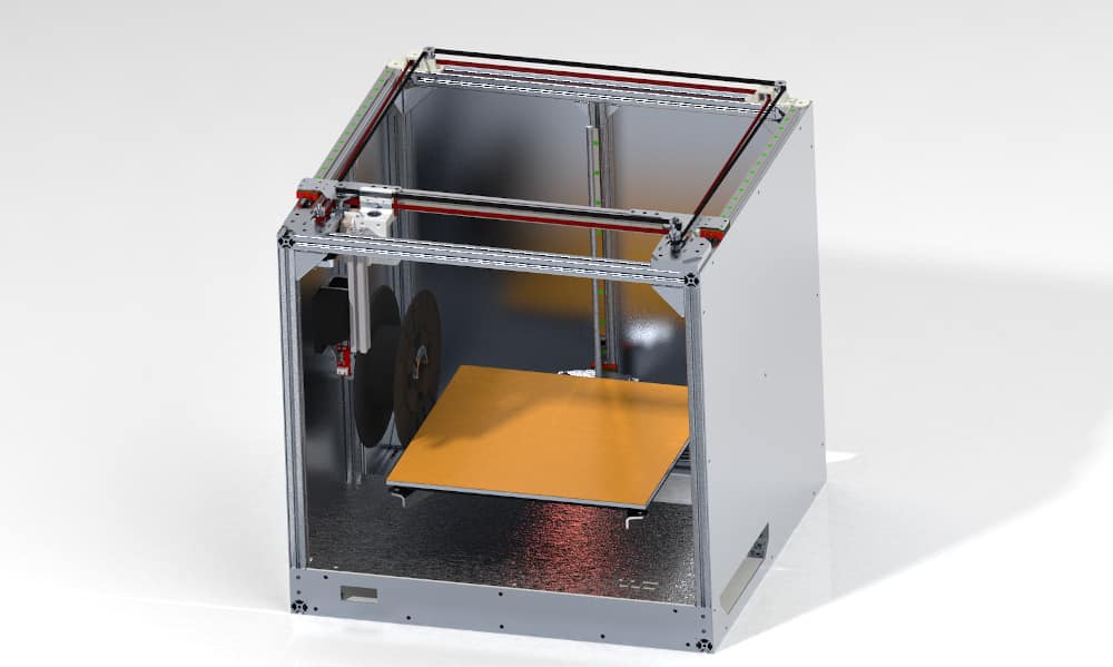
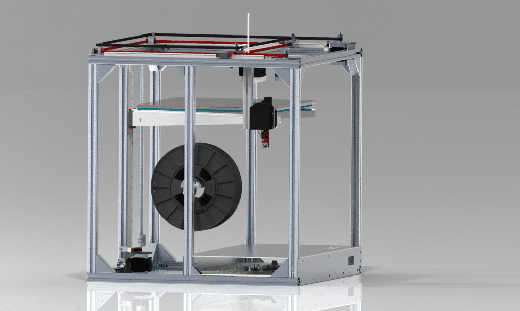
At some point in time every (nowadays so-called) Maker needs a 3D-printer of some sort. In this short article, I want to show you my design which is capable of printing 326x326x300mm sized parts. The focus was on maximum print/build quality while keeping the design as simple, cheap and compact as possible.

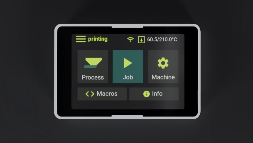
My custom 3D printer display for RepRap (Duet) based printers is now available!
visit https://reppanel.com for more information 🙂
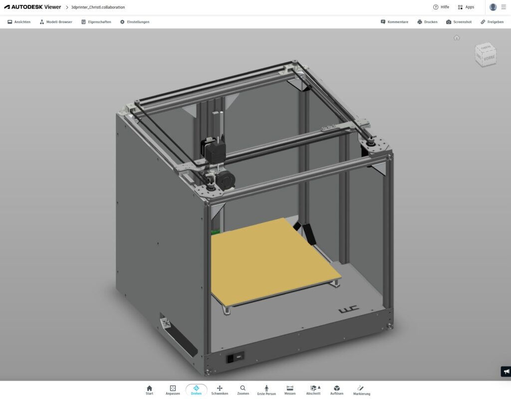
3D Model of the final and latest design
Please follow this link to get to the Autodesk online viewer: https://autode.sk/3reQ7SC
Goals/Requirements
- Max. package: 550x490x500 mm
- Min. print volume: 300x300x300 mm
- Budged: 1500€ – 2000€
- Fast print speeds: >100 mm/s
- High quality prints: Equal of better than other printers in that price range (Ultimaker 3, RailCore II, Zortrax M200, etc.)
- Capable of printing engineering-grade materials (ABS, Nylon, etc.)
- Option to upgrade to multi-material printhead
- Easy to manufacture: No access to NC-Machines
The requirements listed above mainly originate from the fact that I need the printer to be big enough to produce highly integrated (high quality) parts for my drone(s). At the same time, it needs to fit inside something like a kitchen cabinet since this is the only place where I can store the printer for now.
After some research, I found that none of the commercially available printers like the RailCore, Ultimaker 3, Zortrax M-series or Prusa can fulfil all those requirements. The RailCore II 300ZL seems to be a nice machine, but with shipping and up to 19% import duty to Germany I felt like it is a bit expensive.
System Design
The basic design follows the concept of a CoreXY. It is superior to other designs like the Prusa Mk2/3 in regards to rigidity, print volume to printer footprint ratio and max. possible speed. That is why a lot of manufacturers use it for their higher quality products with print beds >=250 mm.
Since I am not the first one to build a CoreXY it is worth taking a detailed look at other designs. The following design is heavily inspired by the HyperCube, RailCore II 300ZL and E3D Motion System (Toolchanger). The latter is a great machine with a thoughtful design but seems to be heavily over-engineered (and thus expensive) if you plan to use it for the sole purpose of FFF. I tried to combine as many advantages of those printers as possible. A good source for 3D printer designs is also openbuilds.com. I might add this design when it’s more refined.
In order to meet my requirements, the following additional (derived) requirements are needed. Those strongly influence the overall design of the system.
System Definition & Derived Requirements
- No CNC machined parts
- No 3D printed parts for parts subject to higher mechanical loads
- Use of laser/waterjet cut parts combined with bending when necessary
- Genuine high-quality linear rails on all axis
- Bowden style extruder with upgrade option to direct drive extruder
- Low probability of burning down
Laser cutting services are broadly available online and are very cheap compared to CNC machined parts. However, the shape and position tolerances are higher compared to NC parts. This will be taken into account. Many laser cutting services also offer a service for bending the cut sheets. The extra costs are still much lower than for a CNC job. Bent parts allow for a more integrated design.
Mechanical Design
In this section, I will go into some details regarding the design decisions of the main components.
Frame
All components must be mounted inside the frame to allow the printer to be insulated to trap the heat inside in a later stage. The frame will be made out of 20x20mm aluminium system profiles. Those are commonly used with 3D printers because of their excellent price to performance ratio. They come in at a few cents/100 mm. Taking a look at the corresponding tolerance norm for aluminium extruded profiles you can find the EN 755-9 and EN 12020-2. The latter one is 50% more restrictive and profiles are often referred to as precision profiles. Profiles following these norms are guaranteed to be at least that precise.
The linear rails will be mounted directly to the profiles making the straightness tolerance of the profiles one of the key values to guarantee smooth movement and low variation in z-direction of the nozzle (XY-Gantry). EN 12020-2 requires profiles with a length ≤ 1000 to have a max deviation of 0.7 mm. Additionally, on a segment of 300 mm length the max. deviation between the highest and lowest point must be ≤ 0.3 mm. Looking at typical FFF layer heights (~0.2 – 0.3 mm) this still sounds like a lot, but bed levelling and tighter actual tolerances of the profiles will make up for the most of it. HIWIN rails require surfaces with much lower tolerances (~≤ 0.05 mm). That is why CNC machined parts are still the best (and most expensive) option. That is why I want to keep this option. For now, the linear rails will be mounted to the extrusions by only two screws. Since we use genuine high quality rails, the chances are good that they have lower tolerances than the extrusions. By only fixing them at both ends to the profiles, the rails will not bend with the mounting surface but keep their current flatness.
To reduce the cost for skews and sliding blocks, high volumes should be bought. This requires a reduction in part variants meaning screws with a certain diameter and length should be used in as many places as possible. Sometimes you just need a few screws of a specific length. In that case, I buy longer screws in bulk and cut them down to the perfect length.
The Frame is designed so that parts of it can be assembled individually and later brought together for final assembly. In this case, it means that the XY-gantry, electronics plate, as well as the Z-Axis, can be assembled without the need for the other components. In case one wants to increase the build volume in z-direction it is only necessary to exchange four aluminium extrusions together with a longer rail and lead screw. The gantry does not have to be disassembled for that purpose.
To increase the rigidity of the frame when printing at higher speeds, I added back- and side panels. The profile for the Z-Axis is an 80mmx20mm profile to reduce torsion and bed vibrations. The first version had a 20x20mm profile instead. The wider profile significantly increases the overall stiffness.
Z-Axis

The Z-Axis consists of a single linear rail. Unlike the E3D Motion System/Toolchanger, this design uses a standard rail (not the wide one). The standard rails can take enough static & dynamic moment in all directions. In reality, the load is almost static and only in z-direction. By only using one linear rail the complexity of the system is reduced while reliability and accuracy are increased. Compared to two linear rails/rods this design is less prone to jamming and much easier to align & assemble. Make sure your rail assembly is pre-tensioned. Otherwise, the movement of the printhead will cause the bed to oscillate in the XY-plane.


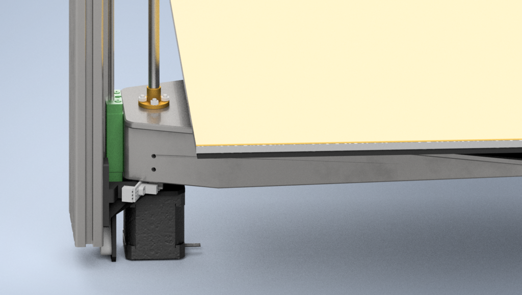
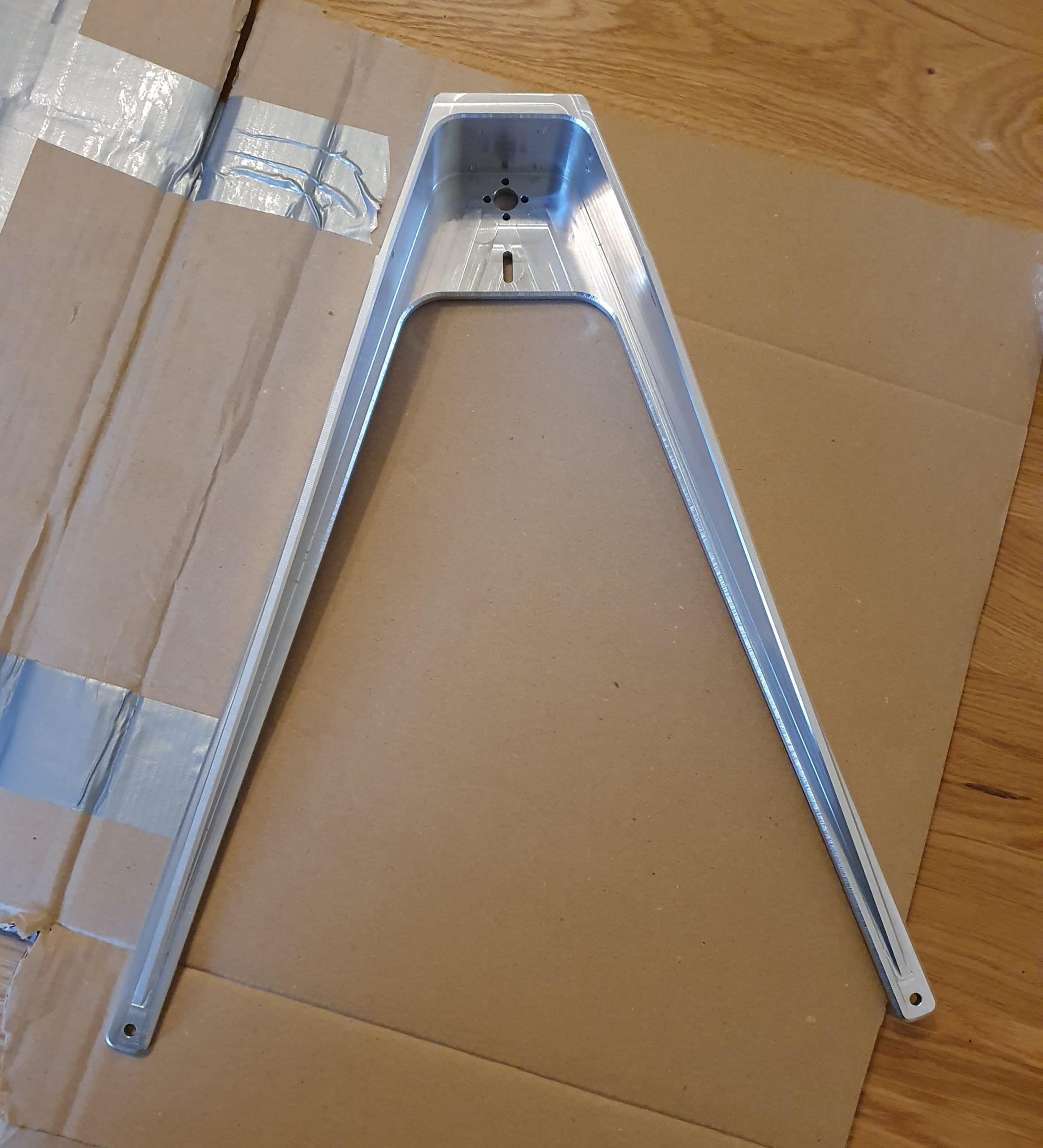
The first design iteration used a bent aluminium sheet to create a mount for the bed. This design turned out to be not stiff enough. I invested in a ~350€ upgrade later and had the bed mount machined in one piece. When designing the z-axis with just one linear rail and lead screw this seems to be necessary to get the desired stiffness. It turned out to be the most expensive part but on the other hand, we save an additional linear rail and complex motor setup to drive two lead screws. If I would do a re-design I would probably go for two linear rails in the back to support the bed, although the current design is already sufficient stiff.
The deformation of the print bed can be further reduced by using a stiffer material like steel. In many cases however the print bed is made from aluminium which has a higher coefficient of thermal expansion (CTE) than steel. This might result in internal stresses and unexpected bending of the print bed mount during heat up.
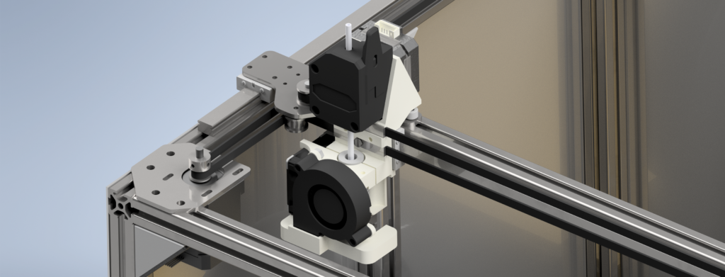
XY-Gantry

The heart of my CoreXY design is based on laser cut parts and aluminium extrusions. As others already showed, it is important to properly align the belts. Some belt paths must be parallel to the XY-movement of the printhead.

The gantry uses a 6mm wide 2GT Powergrip belt from Gates together with Gates pulleys and idlers. As stated by others it is important to first design the basic belt path, then order the belt with pulleys and then measure the diameter of the belt when wrapped around the pulley. Now you can adjust the position of your idlers in the design to make sure the belts run in parallel to the corresponding axes.
The design uses stacked belt paths. By stacking the stepper motor on one side the upper belt path can be designed in a way so that it goes around the top of the linear rail carriages. This allows for simple, but strong laser parts with no further modification/bending required.


The idlers in the back of the printer need a rigid mount to keep them from bending. The idea was to use an open square tube with holes to mount the idlers with threaded rods. This all-metal design promises to be very rigid, cheap and easy to manufacture. The most tricky part would be drilling the holes at the exact positions to guaranty a parallel belt path to the Y-Axis. Since the delivery was delayed and I had no drill press at hand I decided to design alternative mounts to be manufactured using SLS together with some other parts I needed. The SLS parts are expected to be sufficiently stiff.
Because of the high tolerances in steel sheets used for laser cutting (surface flatness) we use an aluminium profile for the x-axis carrier. The rail is mounted on the side to gain more build volume in y- & z-direction while keeping the max. package dimensions.
As of version 1.2 of my design the idlers on the X-axis are mounted using dowel pins instead of M5 screws. Together with an adequate fitting, that is the proper way to mount bearings/idlers. The dowel pins come with an internal thread on one side making assembly easy. This mounting method increases the lifetime of the idlers and lowers noise.
Print Head

The print head will be 3D printed for the most part. I found a very affordable 3D printing service online. This allows me to go for an integral design approach and keep the moving mass as low as possible. Other than that there is not much to say about this part. The belts lock into the printed groves. They are kept in place using two metal plates. Assembly is a bit tricky since you kind of need 3 hands to slightly pre-tension the belts, but apart from that, it works just fine.
In version 1.2 the printhead was redesigned so that a 40x40x10mm Noctua fan can be mounted. The Noctua will replace the E3D hotend fan because the latter one is way too noisy and vibrates like hell. A new part cooling fan duct makes sure the air mainly cools the part, not the hotend.
The latest design iteration of the printhead is a direct drive setup. Thanks to the improved stiffness of the bed there is no speed penalty compared with the bowden design. The bowden design was limited by the high amount of pressure advance required to get high quality prints. While the print quality was good, it is now even better with the direct drive. Especially small and short print segments are a lot more detailed. I personally would only consider bowden for smaller printers in the future, where the length of the tube is not as long (maybe <300mm) and thus the pressure advance setting is not slowing down the setup. My direct drive printer is now even faster than the previous bowden setup, thanks to the reduced pressure advance setting. I could change from 0.7 PA down to 0.02 PA.
Parts List (Basics)
- 24V 150W Meanwell power supply
- 24V E3D V6 Hotend 1.75mm with bowden adapter
- BondTech BMG Extruder with bowden adapter
- FilaFarm 326×326 build plate with FilaPrint surface and heater
- 3x 0.8°/step stepper motors for a more silent operation
- 1x 49Nm stepper motor
- Duet3D Duet 2 Wifi
- 6mm Powergrip 2GT belt
- Powergrip idlers
- Laser-cut parts, Aluminium extrusions, etc.
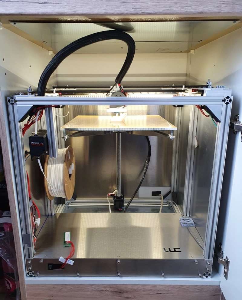
Some Parts Arrived


Some pictures of the current build. Side-panels are mounted and add quite some stiffness and style to the printer. The new printhead looks great and performs as expected. It is super quiet now thanks to the Noctua fan.


Print Quality
As for overall print quality, the design lives up to its expectations. The layer stacking is perfect, which means no layer shifts etc.. I did quite some 18-24h prints and never had an issue. Thanks to the high-quality print bed, three-point levelling and print surface there is no need for mesh bed levelling. I still do mesh bed levelling it anyways to get a perfect first layer. Also, set up time is reduced. For levelling I do not use positions directly above the levelling screws, but ones slightly inwards of the print bed. My print surface is not perfectly level/flat directly above the screws (+-0.05mm). I use the screw in the back (near z-axis) as a reference for levelling all the others. The one in the back is fixed and defines the ultimate max Z that I write into my config files.
Current print settings for quick drafts:
| Setting | Value |
|---|---|
| Default print speed | 70 mm/s |
| Outer shell speed | 50 mm/s |
| Jerk X/Y | 1060 mm/min |
| Acceleration X/Y | 3500 mm/min |
| Travel Speed | 300 mm/s |
Update: The lastest design iteration with the direct drive print head does a Benchy with 20% infill and 0.2mm layer height in 20min. And it looks flawless.
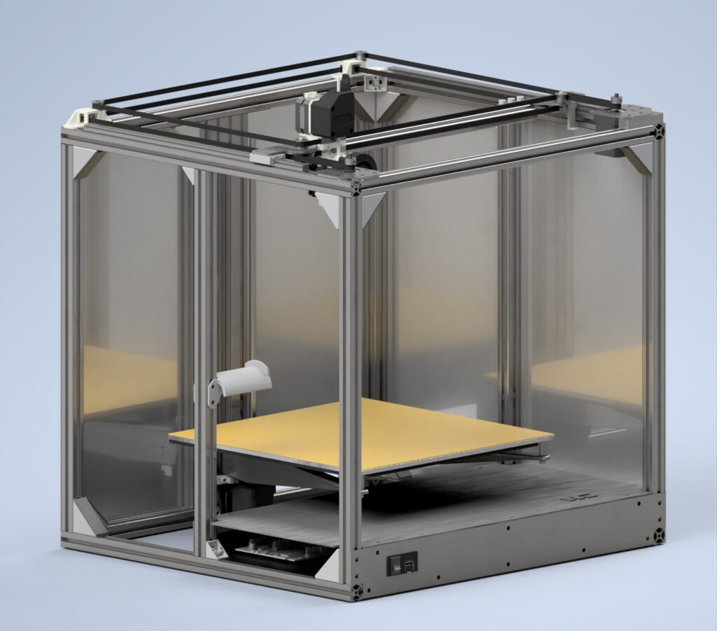
Enclosure
The enclosure is a non-trivial part of the project since I want to print engineering-grade materials and do not have a workshop where I could simply place the printer somewhere. The enclosure traps parts of the heat (heat camber) which reduces warping during the printing process. At the same time, it prevents my girlfriend from throwing a tantrum when it is tucked away somewhere in a nice box in our apartment.
A spare kitchen cabinet is the enclosure of choice. To prevent my apartment from burning down I plate the ceiling of the cabinet with thin steel sheet metal. The sheets are mounted using screws and steel washers between the wooden ceiling and the metal. The resulting air gap and small contact points function as a kind of heat brake in case the printer catches fire and heats the metal. The printer’s side walls are already made out of metal so no need for further protection here. Besides that, all electronic components are hidden within a steel box. The chances of a fire actually being able to spread are very low. Still, it is good to have a smoke detector within the box (watch max operating temperature!) and a fire extinguisher (with a suitable extinguishing agent) nearby.
I also plan on using a small HEPA air purifier to go into the box. Thanks to COVID those are pretty cheap and easy to get by.
Challenges/Problems
The first design iteration worked just fine but some problems were visible early on. This chapter focuses on what kind of challenges I had not anticipated with my first design iteration and shows how I solved them.
X-Y Wobble Of Print Bed
Long story short: Make sure the mounting surface of the print bed mount is flat and not bent due to the manufacturing process. For the Z-Axis you must use a beefy pre-tensioned linear guide. I also advise to go for a machined bed mount and a beefy 80x20mm profile to support the linear rail. All problems listed below are gone thanks to those changes. It also shows that single z-rail setups do work.
The bigger problem resides within the z-axis. It is not stiff enough in Mx direction. The print bed tends to wobble in the printer’s x-direction when touched slightly. Rapid movements of the print-head could cause the same, thus making the machine very slow or creating very low-quality parts.
I think the instability roots within two things.

One being the bent build-plate mount. Its mounting surface towards the linear guide block is not perfectly flat. The bending process causes the surface to have a slight curve. Screwing the mount to the guide block causes the block to bend slightly as well. Because of that, the pre-tension of the block on the rail gets lost and a slight gap between the bearing balls and the rail forms. That causes a slight play within the mounting system. Bad.
I was able to fix most of that by filing the surface until it was flat. That removed the play. Adding washers also worked. However, the built plate is still not as stiff as I want it.
The second thing is the bearing itself. I guess it’s just not stiff enough. In design-phase, I thought the stiffness of the MGN12H block is sufficient since the bed does not experience higher loads in x-direction during print. I assured myself that the block gives in and not the rail or aluminium profile. Looking at alternatives the next best options are: MGN15C, MGN15H or the wider blocks MGW12C and MGW12H. According to HIWIN the max. static moment and rated load for those is higher. I do not want to order a new build-plate mount. This means the new block must not be too different from the MGN12H when it comes to mounting holes and height. From what I can see, the E3D Motion System uses an MGW12H block with Z1 pre-tension. That one is harder to source and a lot more expensive than the N-Series. A problem that perhaps could have been avoided looking at the radial rigidity of the blocks in the first place. I could not find any data on moment rigidity.
| Radial rigidity | |||
|---|---|---|---|
| Load Class | Series | Preload – Z0 [N/μm] | Preload Z1 [N/μm] |
| Average load | MGN12C | 44 | 56 |
| High load | MGN12H | 63 | 81 |
| High load | MGN15H | 87 | 113 |
| Average load | MGW12C | 63 | 81 |
| High load | MGW12H | 89 | 114 |
The deformation can be calculated as follows:
| d=P/k | d Deformation [μm] P Operating load [N] k Rigidity [N/μm] |
The effect is multiplied by the length of the print bed in the y-direction.
It looks like picking the MGW12C Z0 series instead will not help us much. The MGW12H Z0/1 series got wider mounting holes than my current block. I might not be able to get the new holes next to the old ones. The MGN15H Z1 series got the same stiffness as the MGW12H Z1 (used by the E3D Motion System). I’ll pick that one because its dimensions are the most similar of all options to my current setup.
Couldn’t find them online so I wrote an email to an online shop that already sells HiWin products for a fair price. They were kind enough to order me the pre-tensioned variant. I’ll post an update once I tested the new ones.
Update #2: I designed an improved bed mount that I got machined using Xeometrys service. To be honest, to machining quality could be a lot better and is below what they specify but the part will still be able to perform accordingly so I decided to not file a complaint. With the new bed mount the z-axis is almost rock solid. You can still move it slightly in XY-direction with your finger, however during prints the wobble is completely gone. I am currently running at jerk values of 1060 mm/min and accelerations of 3500 mm/s². I think I could go even higher on acceleration.
The new print bed also improves the stiffness in the z-direction. Placing a 950g weight at the center of the bed causes a max. deviation of ~0.10mm of the bed. The deviation was measured at the front edge of the bed where the highest displacement takes place.
Update #1: The print table is a lot more stable now, thanks to the pre-tensioned guide blocks. It’s still not super rigid but seems OK for the job. The remaining wobble might originate from the design again. The top plate that attaches to the z-screw should keep the arms stiff and in place. The print surface is 6mm thick but only mounted using three screws. The design allows for the print-bed to slightly shift, which partly leads to the described wobble effect in XY-direction. Some additional stiffeners in X-configuration mounted further upfront should finally minimize the movement.
Noise
Update #3
Replacing the 1.8° stepper motors for the X/Y Axis with 0.9° steppers made all the difference. The natural frequency of the beams is not hit directly anymore. The printer is now unhearable behind closed doors. Not as silent as a Prusa, but as silent as it may get considering all the metal parts and the size of the printer.
Replacing the stock E3D v6 fan with a Noctua one made a massive difference. The radial part cooling fan does a good job at cooling and producing air pressure however, it vibrates a lot at max RPM. The good thing is that ~40-50% fan speed seems to be enough for PLA.
Most gantry movements are quiet. However, there are some vibrations when it’s moving in certain directions. I checked everything but couldn’t identify the exact problem. My best guess is that either the bearing block or the gantry beam is the root cause. The bearing block is not pre-tensioned, so it could be that the bearing balls are starting to vibrate during specific movements. My other guess is that due to the length and design of the gantry beam (three parts including extruded profile) hit some resonance frequency. I’ll try to re-align the two Y-Rails with a dial gauge and adjust the belt tension so it is “perfectly” equal on both belts. We’ll see how that changes the noise level. Big printers/structures always tend to be louder during operation than smaller ones.
All in all, I am already very pleased with the noise level. I tested the printer within a closed kitchen cabinet and behind the closed kitchen door. The result is you can barely hear it. Only slightly when operated at speeds that hit the resonance frequency of my frame (~35mm/s).
Really nice project!
A good source for 3D printer designs
Overall a very impressive build and documentation, congratulation !
Because you can’t detail everything I have some questions.
The first one is about the y carriages. Is the high precision of the dowel pin sufficient to prevent the lower belt pulley from just falling ? Maybe the motor pulley and front pulley that are fixed play a role.
The second one is about the detailed BOM. You’ve mentioned it but I can’t manage to find it.
Again, that’s a really valuable article you’ve made available for free, I and probably the 3d printing community can say thank you.
Thank you 🙂 I still need to work out some things like the print bed mounting table and noise (maybe more equal belt tension on both belts changes something).
About the pins: The dowel pin forms a transition fit with the pulley bearing. They do not go anywhere belive me 😀 I actually had to mount them by hammering the bearing down a bit. If I remember correctly my pins are rated “m6”. That is more than you need for such a small bearing, but these pins work as well and they are easier to source. Quick tip for assembly: First screw the pins to the metal plates like in the image. Add some screw adhesive so they do not loosen during assembly. Once the bearing is on you will have a hard time fastening the screw again since you can not get a hold on the pin to stop it from rotating.
You are right about the BOM. I try to add it sometime this week. I also plan to release the CAD files, but I want to see what I can do about the bed first.
You’re welcome :p
Yeah the noise is compressed in the video and we can’t appreciate it x)
For the print bed you may be interested in the Jubilee project. The use of 3 separate stepper motors allow true automatic bed leveling (klipper support it at least, I’m pretty sure duet to). The Voron V1.8 kinda does the same thing but with only 2 steppers and a manual knob for the other point of adjustment. It’s nice because it’s way more tolerant to misalignment of the linear guides or flatness inconsistencies of the sheet metal. See by yourself :
https://youtu.be/a9irK9rOUHY
https://github.com/machineagency/jubilee/blob/master/frame/assembly_instructions/frame/build_plate_assembly.pdf
https://youtu.be/R2wU3If3KUA
I’m happy to hear you’re planning on releasing the CAD files ! I will study them and then they will go into my collection with the Voron, the railcore and my cartesian ^^ A BOM is just informative, this is not a project meant to be build as an exact copy soooo don’t be to perfectionist about it 🙂
About the dowel pins, I find my self struggling to find a shoulder bolt that fit the 5mm bore pulleys. Great to see you’ve find a way to do it properly, even if that require a specific order of operation. I don’t plane on getting near those high temperatures, but do you know if an “m6” transition fit can hold up in a heated chamber ? I was thinking 50 to 60°C for abs and maybe up to a hundred for some nylon stuff.
I always found these multi Z-axis designs for auto bed levelling too expensive (multiple linear guides, motors, lead screws etc.). In order to get them right you also need a proper/complex design like the ones you list here.
In my case, the entire bed + mount is made from the same material so everything is expanding/retracting by the (roughly) same amount. The print bed is also 6mm thick – that helps as well. Additionally, I only do have one mount point to the frame, not limiting the expansion. So no bed bending etc. here.
I just didn’t see the benefit of those setups considering you can get a perfectly level bed with the traditional 3 point mount. Once you levelled it manually, you will only need to check every few weeks – not before every print job. But, if you want to avoid the “bed-wobble-issues” that I got with my first designs, the 3-point auto bed levelling stuff might still be the best way to go.
Since I am guessing both (bearing balls + cage and the dowel pins) are made from steel, they should (thermally) expand by the same rate thus keeping the pre-tension and a secure connection.
Yeah I’m with you on the complexity and heat expansion aspect and I thank you for highlighting that. In that regard I’ve checked for genuine Hiwin Rails and found out that in France the big HG ones are as much or less expensive than the MG series for comparable load. If I was someone building this machine from the ground up I think I would have gone for one of these instead of an MGN15H.
Detailed specifications here : https://www.hiwin.com/pdf/linear_guideways.pdf
In short, they have about the same requirement for the mounting surface flatness and a better Mp moment :
MGW12H –> 57Nm (e3d tool changer)
MGN12H –> 36Nm (your first attempt) ~100€ for carriage + 200mm rail with taxes and shipping fee
MGN15H –> 57Nm (your updated z axis) ~ 100€
HGH15CA –> 100Nm (the one I would get) ~80€
HGH20CA –> 200Nm ~80€ (why not)
With the use of a 3 point leveling system, you’re machine may confirm this z axis design as the good enough middle ground we all want.
In tandem with you’re own experience, cloud you also do some dial indicator measurement ? I’ve heard e3d saying a 250um deviation at the tip of the bed for a 4kg distributed load. I know it’s not the same moment arm and rails but that what’s interesting !
The 3d printers I’ve mentioned tends to use inexpensive linear rails to make the “proper” design cheaper. But still, like you said those additional motors, leadscrews and electronics kill it and in the end it’s more expensive than the one rail approach.
Though with their 0.02mm layers at 75mm/s the Railcore project really demonstrate that this is can be the best way to go to fix the “bed wobble issues”. If design properly to consider the thermal expansion of the system of course, it should not add to many problems.
Hi, I really like your deisgn: simple but functional and i want to recreate it with some modifications. Sadly the CAD files are expiried, can you re-upload it (maybe on github)? Thank you very much.